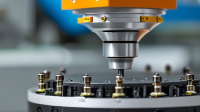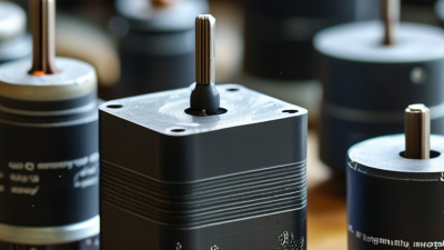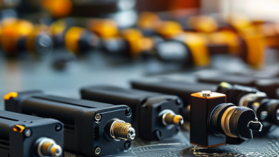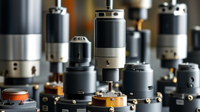
A Piezoceramic Actuator converts electrical energy into precise mechanical movement. It uses a piezoceramic element, often lead zirconate titanate (PZT), that changes shape when voltage is applied. The movement may be only a few micrometres. Yet it can position optics, valves, medical components, and semiconductor tools with exceptional accuracy.
Kenji Uchino, a leading piezoelectricity researcher, describes the principle clearly: “Piezoelectricity is the coupling between mechanical and electrical phenomena.” His work in Piezoelectric Actuators and Ultrasonic Motors remains an important technical reference. In practical terms, an alternating voltage makes the ceramic expand and contract. A stack design adds these tiny movements together. A bending design creates larger displacement. The actuator responds quickly, often within milliseconds.
Commercial interest is expanding. MarketsandMarkets reported that the global piezoelectric devices market was valued at approximately USD 32.3 billion in 2023. The same report projects continued growth through 2028, supported by automation, healthcare, aerospace, and consumer electronics. Grand View Research also identifies rising demand for precision motion and sensing technologies. These reports measure broader piezoelectric devices, not actuators alone. That distinction matters.
Real performance is less perfect than a datasheet suggests. Piezoceramics can show hysteresis, creep, heat generation, and limited stroke. They also require careful voltage control and mechanical preload. A device may move accurately in a laboratory, then behave differently after temperature changes. Engineers must test the complete assembly, not only the ceramic element. That is where understanding how a Piezoceramic Actuator works becomes practical, not merely theoretical.
A piezoceramic actuator is an electromechanical device that converts voltage into controlled mechanical movement. It uses a piezoceramic material, which changes shape when exposed to an electric field. This behavior is called the inverse piezoelectric effect. In a simple actuator, electrodes apply voltage across the ceramic, causing it to expand, contract, or bend. The movement is usually very small, often measured in micrometers, but it can be highly repeatable.
Its core properties include fast response, high positioning resolution, strong stiffness, and low energy use during static holding. Piezoceramic actuators can operate in stack, bending, or shear configurations. A stack design produces axial motion, while a bending design resembles a thin strip flexing under voltage. The ceramic itself is hard and compact. It also transfers force effectively. These features make the actuator useful for precision valves, vibration control, optical alignment, and fine mechanical adjustment.
However, it is not a perfect motion source. The output depends on voltage, temperature, preload, and mechanical load. Hysteresis and creep can reduce accuracy during demanding positioning tasks. Engineers often use sensors and feedback control to correct these effects. The basic voltage-to-motion model is helpful, but incomplete. Real systems require careful insulation, mounting, and control tuning. Without proper preload, the ceramic may experience damaging tensile stress. That detail is easy to overlook.

What Is a Piezoceramic Actuator and How Does It Work?
A piezoceramic actuator converts electrical energy into precise mechanical motion. Its operation depends on the inverse piezoelectric effect. When voltage crosses the ceramic, charged domains shift slightly. The material expands or contracts along a controlled axis. This movement may be smaller than a human hair, yet it can position components with nanometer-scale resolution.
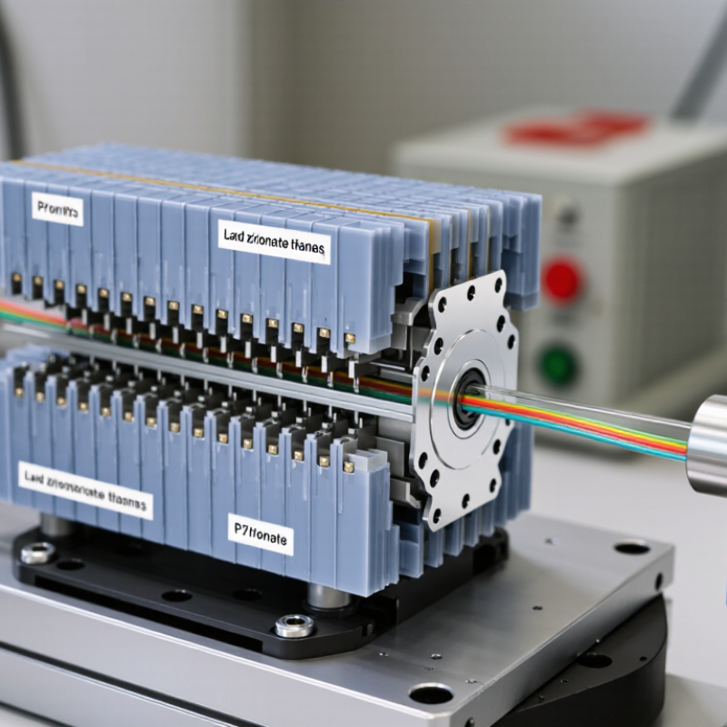
A stacked actuator contains many thin ceramic layers and electrodes. Each layer adds a small strain, increasing total displacement. The basic relationship is S = dE, where S represents strain, d is the piezoelectric coefficient, and E is electric field strength. Industry datasheets commonly report d33 values from roughly 200 to 700 picocoulombs per newton for advanced piezoceramics. A 2024 IDTechEx market analysis also identified precision motion, medical equipment, and semiconductor manufacturing as major growth areas for piezoelectric technologies. However, voltage does not create perfectly smooth motion. Hysteresis, temperature drift, and mechanical load can reduce accuracy. That limitation is easy to underestimate.
Tips: Use a closed-loop position sensor when repeatability matters. Limit the drive voltage to the ceramic’s rated range. Preload the actuator during assembly, because tensile stress can damage brittle piezoceramic elements. Test real displacement under the actual load. Theoretical travel can look impressive. Practical travel may be smaller.
How the Piezoelectric Effect Produces Mechanical Motion
The chart shows the idealized displacement of a 100-layer piezoceramic stack as the applied voltage increases. Using a representative longitudinal piezoelectric coefficient of 500 pm/V, the actuator produces approximately 50 nm of motion per volt, reaching about 5 µm at 100 V. Real actuators may show hysteresis, preload effects, temperature dependence, and reduced displacement under mechanical load.
When an electric field is applied, the aligned ceramic domains change shape through the piezoelectric effect. The small expansion of each layer adds together, converting electrical energy into precise mechanical motion.
A piezoceramic actuator converts electrical energy into precise mechanical movement. Its active element is usually a ceramic disc or stacked layer assembly. Thin electrodes sit between the ceramic layers. A metal housing protects the element, while a preload mechanism keeps it under controlled compression. This matters because piezoceramics tolerate compression better than tension. A controller and high-voltage amplifier provide the required electrical signal. Some systems also use a position sensor for closed-loop accuracy.
The operating sequence is direct. The controller sends voltage to the electrodes. An electric field forms through the ceramic. The polarized material then expands or contracts along a selected axis. That small strain moves a shaft, mirror, valve, or precision stage. Reverse the voltage, and the movement reverses. The stroke may be only a few micrometres, but its response can be extremely fast.
Very small movement.
In practical testing, installation quality often matters as much as the actuator itself. Uneven mounting can introduce bending, friction, or unwanted vibration. Piezoceramics also show hysteresis and creep, so the commanded position may not remain perfectly stable. Open-loop control is simple, but it cannot correct these effects. A sensor and feedback controller usually improve repeatability.
I would not treat the rated displacement as guaranteed under every load. Temperature, preload, wiring, and mechanical stiffness can change the result. That limitation is easy to overlook.
A piezoceramic actuator converts electrical voltage into precise mechanical motion through the inverse piezoelectric effect. When voltage crosses its ceramic elements, the material expands or contracts. The movement may be tiny, but it can occur within microseconds. This makes piezoceramic actuators useful in optical alignment, micro-positioning, valves, and vibration control.
Common types include stack, bending, shear, and tube actuators. Stack actuators provide high force and excellent stiffness, but their stroke is usually short. Bending actuators create larger movement through curved deformation. They require less force. Shear designs move sideways and suit compact positioning systems. Tube actuators can produce radial or axial motion, depending on electrode layout. Performance depends on more than displacement. Engineers also examine blocking force, resonance frequency, hysteresis, creep, and operating voltage. Closed-loop feedback can improve accuracy, especially after temperature changes. However, control systems add cost and complexity.
Tips: Match the actuator type to the required stroke and load. Use a suitable preload for stack designs. Avoid exceeding the recommended electric field. Measure motion at the actual mounting point, not only on a test bench. In practice, specifications can look ideal. Real assemblies may perform differently because of friction, cable stiffness, or uneven clamping. Thermal drift is easy to underestimate. Calibration should be repeated under working conditions.
| Actuator Type | Operating Principle | Typical Displacement | Typical Force Range | Typical Frequency Capability | Key Characteristics | Common Applications |
|---|---|---|---|---|---|---|
| Stack Actuator | Multiple piezoceramic layers expand or contract along the polarization axis when voltage is applied. | Approximately 10–100 μm per stack; amplified designs can provide millimeter-scale motion. | Approximately 0.1–10 kN, depending on size and preload. | From static positioning to several kilohertz. | High stiffness, high blocking force, fast response, and low moving mass. | Precision positioning, vibration control, valve control, and structural actuation. |
| Bender Actuator | A piezoceramic layer, or two opposing layers, produces bending through differential strain. | Approximately 0.1–5 mm, depending on geometry and applied voltage. | Typically 0.01–10 N. | Generally up to hundreds of hertz; some designs operate into the kilohertz range. | Large displacement, compact construction, low force, and relatively low drive power. | Microfluidic pumps, optical shutters, relays, buzzers, and small positioning mechanisms. |
| Tube Actuator | Electrodes on the inner and outer surfaces generate radial, axial, or bending motion in a ceramic tube. | Typically a few micrometers to several hundred micrometers. | Approximately 0.1–100 N, depending on dimensions and configuration. | From low-frequency positioning to several kilohertz. | Compact cylindrical form, multi-axis motion potential, and good dynamic response. | Optical fiber alignment, scanning systems, nanopositioning, and precision instruments. |
| Shear Actuator | An electric field applied across the ceramic produces lateral shear strain. | Typically several micrometers to tens of micrometers. | Approximately 1–1,000 N, depending on active area and stack design. | From static operation to several kilohertz. | Useful where lateral motion, compact size, and high stiffness are required. | Fine positioning, optical alignment, scanning stages, and adaptive mechanisms. |
| Ultrasonic Resonant Actuator | A piezoceramic element excites a mechanical resonance, producing traveling or standing waves for motion. | Usually micrometer-scale vibration amplitude at the active surface. | Often 0.1–50 N of drive force, depending on contact and preload. | Typically 20–500 kHz. | High resolution, self-locking capability, compact design, and no conventional electromagnetic coils. | Camera focusing, precision stages, miniature drives, and rotary or linear motion systems. |
| Inchworm or Walking Actuator | Multiple piezoceramic elements alternately clamp, extend, and release to create incremental motion. | Travel can range from millimeters to hundreds of millimeters; step size is commonly sub-micrometer to several micrometers. | Approximately 1–100 N. | Step rates commonly range from tens to hundreds of hertz. | Long travel, high resolution, strong holding force, and excellent repeatability. | Vacuum-compatible stages, semiconductor equipment, microscopy, and precision automation. |
| Multilayer Chip Actuator | Thin piezoceramic layers with internal electrodes are connected in parallel to reduce drive voltage. | Typically 1–50 μm, depending on layer count and actuator length. | Approximately 10–5,000 N. | From static control to several kilohertz. | Lower operating voltage than traditional stacks, high force density, and fast response. | Fuel injection, precision valves, active vibration isolation, and micro-positioning. |
| General Performance Parameters | Motion is generated by the inverse piezoelectric effect: an applied electric field causes mechanical strain. | Free strain is commonly around 0.05–0.15% for many hard or soft piezoceramic compositions. | Blocking force is strongly dependent on stiffness, active volume, preload, and mechanical design. | Electrical and mechanical resonance determine the practical upper operating frequency. | Sub-millisecond response, high resolution, low hysteresis with closed-loop control, and very low static power consumption. | Precision motion, sensing and actuation systems, acoustics, medical equipment, and industrial automation. |
Note: Values are representative engineering ranges for comparison only. Actual performance depends on ceramic composition, actuator geometry, preload, drive voltage, temperature, mounting conditions, and control method.
A piezoceramic actuator converts electrical voltage into precise mechanical movement. It uses the piezoelectric effect inside a ceramic element. When voltage changes, the element expands or contracts by a very small distance. The motion is fast, repeatable, and usually measured in micrometers. A controller adjusts voltage to position the actuator accurately.
Small movement matters.
These actuators appear in optical alignment, precision valves, medical instruments, vibration control, and micro-positioning stages. They can move without gears, motors, or lubrication. This compact structure reduces mechanical wear and supports rapid response. In laboratory systems, engineers often use displacement sensors to correct temperature and load errors. That feedback improves practical accuracy.
However, the benefits have clear limits. A piezoceramic actuator normally provides short travel and limited force. It also shows hysteresis, meaning the same voltage may produce different positions. Temperature, mounting stress, and ceramic aging can change performance. Designers must control voltage carefully, because excessive electrical input may damage the element. Mechanical preload is often necessary, but poor preload can reduce movement or cause cracking. Real testing is essential. Simulation alone can miss wiring effects, friction, and installation errors. Some designs also need an amplifier, sensor, and closed-loop controller, increasing cost and system complexity. The best specification should state travel, force, response time, accuracy, operating temperature, and expected service conditions.