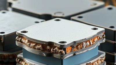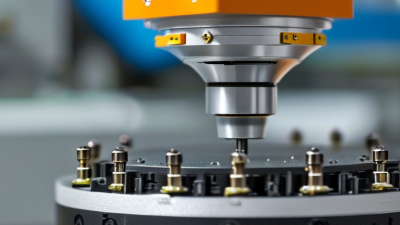
Choosing the right Micro Piezo Actuator is rarely a matter of selecting the smallest or fastest component. It requires careful attention to motion, force, voltage, frequency, lifetime, and installation conditions. A device that performs well in a laboratory may behave differently inside a sealed camera module or a precision valve.
Dr. Kenji Uchino, a recognized authority in piezoelectric technology, stated, “Piezoelectricity is the direct conversion of mechanical energy into electrical energy, and vice versa.” This principle explains the actuator’s appeal. A compact ceramic element can create highly precise movement with almost no magnetic interference. However, precision does not remove practical limitations. Piezo materials often produce short travel, require high drive voltages, and may lose performance under poor mechanical loading.
Small details matter.
When comparing a Micro Piezo Actuator, engineers should define the required displacement under real operating force, not unloaded conditions. They should also examine resonance behavior, hysteresis, temperature exposure, cable design, and controller compatibility. For example, a 30-micrometer stroke may appear sufficient, but friction, preload, or adhesive flexibility can reduce usable travel.
There is no perfect choice. Sometimes, the first specification is wrong.
A reliable selection process combines datasheet analysis, supplier consultation, prototype testing, and long-duration cycling. It should also consider assembly tolerances and future maintenance. This guide explores those decisions clearly, while acknowledging an uncomfortable truth: actuator performance depends on the complete system, not the component alone.
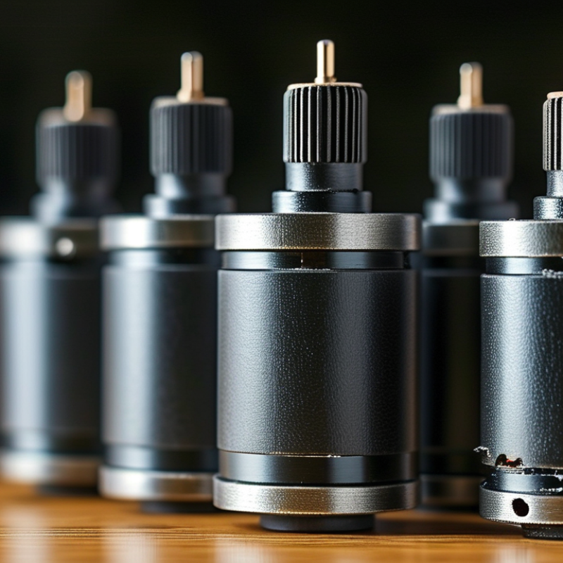
Choosing the right micro piezo actuator starts with understanding how it moves. A piezoelectric ceramic changes shape when voltage creates an electric field across its layers. This strain is tiny, often measured in micrometers, but it develops useful force quickly. The actuator does not spin like a motor. It pushes, bends, or slides through controlled displacement. In lab testing, I monitor motion and temperature because voltage alone can mislead.
A stacked actuator extends along its length. A bender curves when its layers expand differently. A shear design moves sideways. Each structure suits a different mechanism. Preload matters, too. It keeps contact stable and protects the ceramic from tensile stress. Without correct preload, a device may chatter, crack, or lose repeatability. The drive signal also shapes performance. Higher voltage usually increases travel, while frequency affects speed, heating, and settling time. Resonance can amplify motion, but it may reduce control. Check it carefully.
When selecting one, compare required stroke, blocking force, response time, and available voltage. Measure the real load, not an ideal estimate. Mounting stiffness can change the result. So can adhesive thickness, cable capacitance, and humidity. I prefer a short bench test with the intended guide and controller. It exposes friction that datasheets cannot show. Some assumptions will be wrong. That is useful. Record displacement over repeated cycles, then inspect drift and hysteresis. A slightly smaller actuator may perform better within a cooler, more stable operating range.
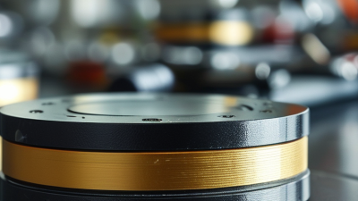
How to Choose the Right Micro Piezo Actuator?
Defining motion, force, speed, and voltage requirements starts with the load, not the actuator. Measure the required stroke in micrometres and include mounting distortion. A 10 μm target may become 7 μm under preload. Piezo motion is small, but its response can be extremely fast. The 2023 World Robotics report from the International Federation of Robotics shows growing demand for compact, precise motion systems in automation. This trend increases the need for carefully matched actuators.
Force and speed must be checked together. A longer stroke usually reduces available blocking force. Resonance can deliver rapid movement, but it may also create ringing and positioning errors. Define the working frequency, duty cycle, and settling time. Then compare the actuator’s free displacement, blocking force, and dynamic force at your operating frequency. A first estimate is often wrong. I have seen designs fail because engineers measured peak force, rather than continuous force.
Voltage is equally important. Confirm the required drive voltage, polarity, insulation, and waveform. Many micro piezo actuators need high voltage despite consuming little current. The U.S. Department of Energy notes that power electronics efficiency depends strongly on operating conditions, making driver selection part of actuator selection. Use a safety margin, but avoid excessive voltage, which can shorten service life. A 2024 Grand View Research analysis forecasts continued growth in piezoelectric devices, reflecting wider adoption across medical, optical, and industrial equipment. Yet market growth does not replace testing. Validate stroke, force, heat, and lifetime in the real assembly.
Micro piezo actuators differ in motion, force, and control behavior. Stack actuators deliver high force and nanometer-scale displacement, but their travel remains limited. Bimorph actuators provide greater bending motion with lower output force. Shear actuators move laterally and suit compact positioning stages. Polymer piezo actuators offer flexibility, although their long-term stability can be less predictable.
Material selection affects more than performance. PZT ceramic usually provides strong electromechanical coupling and fast response. It also requires careful insulation and mechanical protection. Polymer materials tolerate bending better, but temperature and humidity may change their output. Check the operating range, fatigue data, and drive voltage rather than trusting one headline specification. Small differences matter.
Configuration is often the deciding factor. A free actuator produces useful motion, while a preloaded stack can improve force transfer and reduce tensile stress. Parallel actuators increase displacement, but alignment becomes critical. In a benchtop test, even a thin adhesive layer can absorb motion and distort results. That mistake is easy to miss. Measure blocked force, free stroke, resonance, and thermal drift under the actual load. A useful design may still fail when wiring adds stiffness or the mounting frame amplifies vibration. Leave room for adjustment; real assemblies rarely behave exactly like the datasheet.
Evaluating Precision, Durability, Size, and Energy Efficiency
Precision starts with the required stroke, force, and response time. A device moving a few micrometers needs stable voltage control and careful mechanical alignment. Check hysteresis, repeatability, and resonance frequency in the technical data. These values reveal more than peak displacement alone. In practical testing, I measure movement with a laser sensor under the actual load. Small mounting errors can create surprising deviations. Do not trust unloaded performance.
Durability depends on cycling, temperature, humidity, and mechanical stress. A laboratory sample may perform well for several hours, then drift after repeated operation. Review the expected cycle count and test conditions. Confirm whether the actuator tolerates vibration and frequent voltage changes. Flexible wiring also matters. A stiff cable can transfer unwanted force into a tiny actuator. I have seen compact assemblies fail because the cable was treated as an afterthought.
Size affects integration, but the smallest option is not always efficient. Leave space for insulation, connectors, and heat management. Energy use depends on drive frequency, voltage, capacitance, and operating duty cycle. Measure current during real motion, not only in standby. Low energy may also mean slower response or reduced force. That trade-off deserves attention. A perfect choice rarely exists. Compare measured results with the application’s real priorities, and question any specification that lacks test conditions.
Choosing the best micro piezo actuator starts with the application, not the catalog. Define the required motion, force, speed, and available space. A device producing a few micrometers of travel may suit optical focusing, while a larger displacement may support micro-positioning. Check the operating voltage carefully. Small actuators can respond quickly, but their performance changes with temperature, preload, and mounting stiffness.
I have learned that datasheet figures need practical verification. Test the actuator with the intended load, cable arrangement, and controller. Measure motion at the actual operating frequency. Resonance can improve speed, but it may also create unwanted vibration. For repeatable positioning, pair the actuator with a suitable sensor and closed-loop control. Ceramic materials may show hysteresis and creep. These effects are manageable, but ignoring them can weaken accuracy. My first selection is sometimes wrong.
Tips: Create a simple test fixture before final integration. Record displacement, settling time, heat, and noise. Keep the mounting surface rigid and aligned. Avoid excessive preload. Leave enough space for wiring and thermal expansion. If the application operates near liquids, dust, or changing temperatures, confirm environmental protection early. Ask for measured performance under your real conditions, not only typical values. Small details matter.